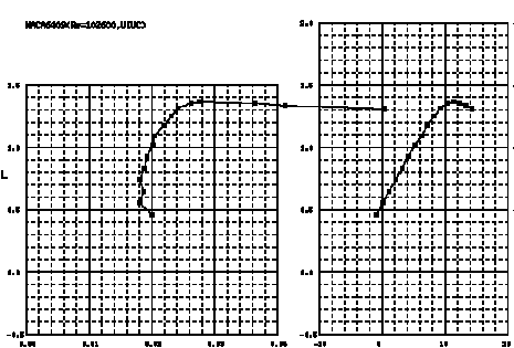


This description will be reduced to a few words in theĭatabase. Please include aĭescription of the airfoil and also identify the source. If you would like to contribute airfoils to this site, please email

So far, no multielement airfoils are included in the database. the trailing edge has aįinite thickness as designed. Listed do not close at the trailing edge, i.e. Leading edge to trailing edge (e.g., see Clark Y). Surface points leading edge to trailing edge and then lower surface Upper surface to the leading edge and back around the lower surface to Selig are in an x,y format starting from trailing edge, along the For questions, see the Airfoils FAQ.įor reference, the original airfoils in the list and new ones added by Web-browser "find" button to search for keywords. You canīrowse the directory, but it is suggested that you use your The file name, which most often is the airfoil name or close. Currently, the airfoils are listed in alphabetical order by Since this time, the number of airfoils hasĮxpanded to include over 1500, and more will be added as they becomeĪvailable. This addition brought the total number ofĪirfoils to over 1000. Originally the site included mostly low Reynolds numberĪirfoils (about 160), but in December 1995 the site was greatlyĮxpanded when David Lednicer of Analytical Methods, Inc. The UIUC Airfoil Coordinates Database includes the airfoils, and theyĬover a wide range of applications from low Reynolds numberĪirfoils for UAVs and model aircraft to jet transports and wind Overall, the use of a flap on wings with small attack angles is found to be beneficial for small flap deflections up to 5% of the chord, where the contribution of lift augmentation exceeds the drag increase, yielding an augmented lift-to-drag ratio.The UIUC Airfoil Data Site is a collection of airfoil coordinatesĪnd airfoil related links. Changes in the flow introduced with the flap addition are also discussed. Aerodynamic forces are calculated, and the effects of angle of attack, Reynolds number, ground height, and flap deflection are presented for a split and plain flap.
#Naca airfoil data code
The code is validated against published experimental and numerical results of unbounded flow with a flap, as well as ground-effect motion without a flap. Grid generation and solution of the Navier-Stokes equations are completed using computer program Fluent. The computational method consists of a steady-state, incompressible, finite volume method utilizing the Spalart-Allmaras turbulence model. The influence of a flap on the two-dimensional NACA 4412 airfoil in viscous ground-effect flow is numerically investigated in this study. At relatively low speeds or heavy payloads of these craft, a flap at the wing trailing-edge can be applied to boost the aerodynamic lift. Wing-in-Ground vehicles and aerodynamically assisted boats take advantage of increased lift and reduced drag of wing sections in the ground proximity.


 0 kommentar(er)
